The animation given below shows Proteus simulation for variable duty cycle PWM signal from Arduino pin D10. PinMode(A0,INPUT) /* ser pin A0 as a input pin */ PinMode(pwm_pin,OUTPUT) /* set pin 10 as a output pin */ *two interger type variables to store digital value and duty cycle value */
#Arduino pwm pin 11 varspeedservo code#
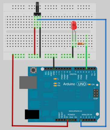
This code generates 0-100% variable duty cycle with the default frequency of D10 pin of Arduino. Also, connect an oscilloscope to D10 of Arduino.Ī=analogRead(A0) /* take analog sample from A0 and store result in variable 'a'*/ī= map(a,0,1023,0,255) /* map the digital value to duty cycle range 0-255 */ĪnalogWrite(pwm_pin,b) /* generate pwm signal on pin10 with duty cycle value of b */ Make connections with Arduino and POT according to this schematic diagram. 11 const int blueledpin 10 const int redsensorpin A0 The number of times. The sequence used to seize timers is defined in timers.h','',' The methods are:','',' VarSpeedServo - Class for manipulating servo motors connected to Arduino pins.

That means that the logic high from the Arduino might not be enough to satisfy the requirement of the fan which is now 0.5V more than normal. In other words, we will map the digital value measured with analogRead() function into duty cycle. Then, ground for the fan, which is the reference point for the PWM input signal will be 0.5V above ground for the Arduino PWM output. To control duty cycle, we will use a potentiometer with analog channel zero of Arduino. The pins 5,6,9,10 (D-Side) work well for PWM, but 19,20 (A-Side) dont. For first tests servos will be controlled for 2 positions (model railway rail switches) by buttons, where JCButton.h is included. We will use D10 pin of Arduino to get output signal. hi, my goal is to control 4-5 servos with 1 Arduino Nano, what needs pwm. In this section, we will learn to generate variable duty cycle PWM. } Proteus Simulation Output Variable Duty Cycle PWM Arduino TCCR1B=_BV(WGM13)|_BV(CS11) /* Activate PWM Phase, frequency correction Mode */įloat frequency=0 /* initially set frequency to zero */

TCCR1A=_BV(COM1A1)|_BV(COM1B1) /* set Fast PWM Mode */ PinMode(outputpin, OUTPUT) /* set as a output put */ * Perform initialization and declarations inside setup() */ void loop()Ĭomplete Code int outputpin=9 /* Assign symbolic name outputpin to D9 PWM pin of Arduino */ Pulse Width Modulation, or PWM, is a technique for getting analog results with digital means. After a call to analogWrite (), the pin will generate a steady rectangular wave of the specified duty cycle until the next call to analogWrite () (or a call to digitalRead () or digitalWrite ()) on the same pin. Can be used to light a LED at varying brightnesses or drive a motor at various speeds. The value of frequency gets updated on the PWM pin after every one second. Writes an analog value ( PWM wave) to a pin. The potentiometer which connects with analog channel zero (A0) of Arduino is used to control set the frequency of the PWM signal. 0.0113 is a factor that restricts the count variable in the range of 10000 to 100000 which results in a frequency range of 10 Hz to 100Hz. Similarly, analogRead() functions reads 0 when voltage is 0V. The analogRead() function reads 1023 when voltage is 5V at the analog pin.

I am guessing that this clash will create problems.Inside the loop() function, the value of OCR1A is being calculated stepwise according to the required frequency formula given above. This means both the SD.h and speaker_pcm want to use pin 11, and the requirement to use these pins is dictated by the hardware. Which takes place on digital pins 11, 12, and 13 (on most Arduino boards) However, this is what documentation for SD.h library says: The communication between the microcontroller and the SD card uses SPI, The sketch mostly works, however I am having a few problems with the 'wait' function in the write command. I wanted to change the program such that the WAV data was read from a SD card. Hello All, I am trying out a simple sketch to make a servo move back and forth between its extents whilst controlling its speed with a pot.

Takes Timer 2 (8-bit)įor the pulse width modulation, breaking PWM for pins 11 & 3. (analogWrite()) for Arduino pins 9 and 10. However, this means that the Pins 3, 9, 10 and 11 can not be used anymore according to the documentation: Takes over Timer 1 (16-bit) for the 8000 Hz timer. On Arduino Uno Rev3, I just ran the speaker_pcm demo that used TIMER1 and TIMER2 to generate a PWM wave.


 0 kommentar(er)
